
NEMA Wiring Schematic Manual for Electrical Experts
Nearly 70% of the electrical breakdowns across facilities stem from substandard wiring practices. These figures accentuates the requirement of following established protocols, highlighting NEMA wiring diagrams’ significance for electrical specialists. Via these drawings, wiring configurations that fulfill both operational effectiveness and optimal safety norms are presented.
The aim of this document is to equip electrical experts with profound knowledge into NEMA norms. Emphasizing the importance of proper electrical setups is crucial. Through mastering these rules, specialists can significantly cut the chance of hazards and confirm they comply with safety standards supported by Installation Parts Supply. Expertise in l 14 30 plug is vital whether creating modern setups or fixing current ones, as it boosts the ability to provide reliable and trustworthy electrical systems.
Principal Learnings
- NEMA wiring schematics are essential for ensuring electrical security and compliance.
- Correct wiring practices can minimize electrical failures considerably.
- Understanding NEMA norms enhances the effectiveness of electrical arrangements.
- Installation Parts Supply encourages compliance with safety standards in electrical work.
- NEMA schematics cover a variety of uses across various fields.
Grasping NEMA Criteria and Why They Matter
NEMA standards are pivotal in the electrical domain, guiding protection and performance precisely. Developed by the National Electrical Manufacturers Association, they define key criteria for developing, evaluating, and labeling electrical gear. Such measures guarantee standardization and dependability across all electrical set-ups, which is of great value.
Identify the NEMA Criteria?
NEMA designations differ from levels 1 through 13. Every level specifies the conditions suitable for electrical appliances to function effectively. For example, NEMA 1 provides minimal indoor safeguarding but does not offer dust protection. Conversely, NEMA 4 ensures devices is waterproof, a must for surviving substantial water exposure. Understanding these classifications is crucial in picking proper appliances.
How NEMA Criteria Are Important for Electrical Protection
The impact of NEMA criteria in guaranteeing electrical security is significant. They play a significant part in reducing electric shock, equipment breakdowns, and fire hazards. Proper adherence to NEMA ratings empowers appliances to operate securely under certain environmental conditions. For external application, NEMA 3 standards deliver protection against the weather, shielding the equipment from harsh climate like rain and snowfall. In regions susceptible to explosions, classifications such as NEMA 7, 8, and 9 are critical for ensuring safety.
Implementations of NEMA Criteria in Wiring Schematics
The implementation of NEMA standards in wiring diagrams is crucial for secure, efficient electrical systems. These schematics employ standardized symbols and structures based on NEMA standards, simplifying the interpretation of intricate electrical configurations. Such standardization is beneficial. It encourages clarity, uniformity, and diminishes confusions, thereby enhancing electrical security across residential and industrial sectors.
NEMA Wiring Schematic Basics
NEMA wiring schematics are vital for electrical experts, making complicated connections unambiguous. They describe the connections and parts in different installations. By understanding the components, categories, and notations of NEMA schematics, electricians can improve their operations in setups and servicing.
Components of NEMA Wiring Drawings
NEMA diagrams comprise essential elements for distinct electrical configurations. You’ll see wiring connection points, connectors, and various hardware for safe linkages. Each piece secures energy is distributed effectively, following security standards.
Categories of NEMA Wiring Schematics
NEMA employs multiple drawings, like linkage blueprints and circuit designs. These schematics depict device interconnections, while arrangements illustrate current flow. Selecting the appropriate schematic facilitates diagnostics and setup.
Frequent Icons Used in NEMA Wiring Schematics
Icons in wiring drawings are crucial for unambiguous conveyance. They illustrate toggles, circuits, and connectors. Understanding these icons assists teams comprehend schematics accurately. This ensures installations comply with NEMA criteria.
NEMA Wiring Diagram Characteristics
For electrical specialists, understanding the core aspects of precise electrical wiring drawings is crucial. These drawings provide both clarity and completeness, aligning configurations with NEMA standards. They demand accurate annotation and proportioning to reduce setup mistakes. This fosters a safer and highly efficient workplace.
Essential Characteristics of Precise Electrical Wiring Drawings
Precise electrical wiring diagrams are vital in electrical projects. They embody important attributes such as:
- Clarity: Schematics should be unambiguous, reducing the risk of misinterpretation.
- Thoroughness: They must include all key parts, junctions, and electrical ratings.
- Adherence to Standards: Adherence to NEMA criteria is imperative for ensuring safety and performance.
- Detailed Labeling: Clear markings on each part are fundamental for comprehension and avoiding mistakes.
- Correct Scaling: The proportions should replicate the true setup to depict the system correctly.
Comprehending NEMA Coupler Configuration
The insight into NEMA coupler layout is critical for forming proper linkages in electrical networks. Knowledge about specific pin setups upholds security and equipment operation. There exists a range of NEMA couplers, designed for distinct voltages and flows, encompassing:
| Connector Model | Ampere Rating | Voltage Rating |
|---|---|---|
| L5-15 | 15A | 125V |
| L5-20 | 20A | 125V |
| L14-20 | 20A | 125/250V |
| L1430C | 30A | 125/250V |
| L620C | 20A | 250V |
| L1430C | 30A | 125/250V |
| L630R | 30A | 250V |
Grasping NEMA connector layouts is essential for secure linkages, improving efficiency. It’s imperative to match connectors with equipment properly using locking or flat blade types, to dodge safety risks.
NEMA Appliance Wiring
NEMA device wiring covers various setups for secure electrical device linkages. These rules ensure that devices operate in unison safely, reducing danger. Grasping the diverse NEMA devices and their wiring is vital for electricians.
Multiple Kinds of NEMA Devices
NEMA categorizes appliances by kind based on power levels and current requirements. Essential setups are:
- 2-Pole, 2-Wire
- 2-Pole 3-Wire Grounding
- 3-Pole 3-Wire
- 3-Pole, 4-Wire with Grounding
- 4-Pole, 4-Wire
- 4-Pole 5-Wire Grounding
These configurations find use in domestic settings and factories, supporting 125V, 208V, and 480V.
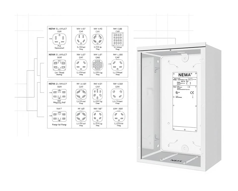
NEMA Outlet Wiring Outlined
NEMA plug wiring differs to accommodate multiple electrical demands, with locking types providing consistent interfaces in shaky conditions. For example, the L5-15 plug works at 15 amps, typical of business sites, whereas the L14-20 is intended for 20 A at 125/250 voltage.
The NEMA designation system helps in choosing the correct plugs, spotlighting features like polarity and grounding. Such accuracy secures that appliances function safely.
NEMA Receptacle Wiring Instructions
Correct wiring of NEMA sockets aligns with electrical standards and safety norms. Such as, L530R receptacles should be wired for 30 A at 125 V, with L630R options for 250 V. Correct grounding is essential to prevent electrical mishaps.
Selecting accredited NEMA plugs and sockets secures safe, code-compliant installations. It’s imperative to check formal guidelines when setting up.
NEMA Motor Wiring and Implementations
NEMA motor wiring is crucial in electrical engineering, especially for industrial use. Understanding how NEMA motor configuration works secures that motors are integrated for optimal efficiency. Motors, like one-phase and tri-phase variants, need correct wiring to function reliably and optimally.
Summary of NEMA Motor Wiring
Grasping NEMA motor wiring demands familiarity of linkages and configurations. Most three-phase motors offer dual-voltage, indicating they can work on both low (208-230V) and high power levels (460V). High voltage wiring results in lower current draw than at low voltage. High voltage advantages encompass thinner cables for the input, a significant benefit for engines exceeding 10 HP.
While both NEMA and IEC appliances are used in the sector, NEMA models are generally larger and more expensive than IEC ones for under 100 HP deployments. NEMA controllers range from size 00 to 9, fit for diverse functions. A common characteristic in NEMA starters is a Trip Class of 20, designed to trigger when a motor’s draw goes beyond 6-fold the Full Load Amperage in 10 secs.
Choosing the Appropriate NEMA Motor Setup
Choosing the right NEMA motor setup affects system operation and security. A typical three-wire control circuit uses three wires for a power control pushbutton station, allowing direct motor management. Common three-phase arrangements comprise the 12 Lead Dual Voltage and 6 Lead, facilitating Wye and Delta arrangements.
IEC motor starters frequently incorporate phase failure detection, boosting safety. They also offer configurable Fault Classes for specific protection in low voltage levels operations. Furthermore, many variants have temperature safeguards, essential for Single Phase and Dual Voltage configurations.
| Configuration Type | Voltage Type | Current Specification | Common Application |
|---|---|---|---|
| 12 Lead Dual Voltage | Dual Voltage (208-230V / 460V) | Dependent on motor size | Applications with Wye Start and Delta Run |
| 6 Lead | One or Dual Voltage | Maximum 32A | Wye or Delta connections |
| Single Phase | Single Voltage | Ranges from 1 to 5 amps | Applications with Two Speed, Two Winding |
| Delta Connection | High Voltage | Depending on setup | Various applications including Current Transformers |
Wrapping It Up
Understanding NEMA wiring diagrams and criteria is vital for electrical specialists aiming to enhance their skills and adhere to electrical safety norms. These principles secure secure and effective electrical setups but also prevent hazards stemming from incorrect wiring. As discussed, following NEMA norms yields the enhanced functionality of various NEMA units and systems.
For electrical professionals, the availability of quality supplies can profoundly influence the result of their tasks. Installation Parts Supply provides a extensive range of wiring products meeting NEMA standards. This allows specialists to obtain vital parts for complying with these key requirements. High-quality resources and comprehensive expertise of NEMA wiring drawings significantly elevate project safety and performance.
During electrical installations, always place security and accuracy as a priority. Gaining expertise in NEMA standards offers the insight necessary for applying optimal procedures precisely. This secures that each electrical connection established conforms to premium criteria.
FAQ
Identify NEMA wiring schematics?
NEMA wiring diagrams display the configurations and junctions of NEMA-standard electrical devices. They adhere to safety and operational criteria set by the National Electrical Manufacturers Association.
Why are NEMA criteria vital for electrical security?
NEMA criteria are essential to setting safety and performance standards for electrical equipment. These principles enable electrical professionals reduce shock risks, equipment failure, and fire risk.
Which elements are crucial in a NEMA wiring drawing?
Essential components in a NEMA wiring diagram consist of electrical layouts and connection schematics. These drawings also include detailed markings and show the electrical system’s various parts precisely for deployments.
What types of NEMA wiring drawings are used?
Various NEMA wiring schematics serve various requirements, including circuitry for power distribution and connector schematics. Each diagram serves a unique role in electrical setups.
Which are the typical symbols found in NEMA wiring schematics?
Standard symbols in these schematics represent toggles, circuit breakers, outlets, and more. Utilization of these symbols encourages unambiguous interaction and correct analysis of wiring diagrams.
Which are the key characteristics of precise electrical wiring drawings?
Correctness in electrical wiring drawings is defined by their transparency, comprehensiveness, and clear annotation. They must align with NEMA norms to avert mistakes in setup.
Explain a NEMA connector layout?
A NEMA connector pinout outlines electrical connections at a connector, indicating particular pin functions. This secures secure and effective junctions in electrical networks.
What are the different types of NEMA appliances?
NEMA units consist of various electrical sockets and couplers, like plugs and receptacles. They are crafted for different ampere and power criteria to satisfy particular application requirements.
Describe how NEMA plug wiring set up?
NEMA plug wiring hinges on defined current and voltage needs, following security protocols and electrical codes for various electrical uses.
Which standards are there for NEMA receptacle wiring?
Recommendations for installing NEMA receptacles stress adhering to electrical standards, ensuring accurate charge alignment, and picking appropriate wire sizes. This ensures both safety and performance in electrical configurations.
How can I wire a NEMA motor effectively?
To wire a NEMA motor, one must understand its specific single-phase or tri-phase arrangement. Choosing the right wiring approach is vital, plus observing electrical protection for optimized motor efficiency.
What must be taken into account when opting for a NEMA motor setup?
Choosing a NEMA motor setup requires an evaluation of the application’s energy requirements and performance traits. It’s also crucial to verify compatibility with pre-existing machinery for assured performance and safety.